|
DINOSAUR
3d Modeling Tutorial
for Lightwave by Russell Gooday
INTRODUCTION
The
following tutorial I hope will give you a detailed insight into how to
approach and
complete the task of building a 3d Dinosaur. For this tutorial I have
chosen an odd
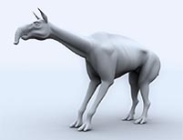
looking beast from the Late Cretaceous called Machrachemia. The techniques
I will
try to explain here, are not just limited to Dinosaurs, though, they can
be applied to
any form of organic modeling.
Please also note, that I have included the quick key references in modeler
and that
they are case sensitive.
SOURCE
MATERIAL
Source
material as you more than likely have experienced can range from detailed
plans, models or photographs to a biro sketch on the back of a cigarette
packet.
On some of the dinos, I have modeled, I have had as little as a URL, leading
to a
photograph of 4 teeth and a brief description of what the rest of the
beast might or
might not look like. However in this example I was fortunate to have scaled
profile
pencil drawings to scan in, taking out alot of the guess work. I would
add it is still
worth looking for extra reference material on a job like this. If you
look at this beast,
you can see that he/she has a body similar to today's camels, so for details,
which
maybe obscured
like
the rear legs in the front on shot, we could look for camel
images, on the web or in books to help fill those gaps.
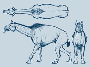
(Click for reference image)
ARE
YOU SITTING COMFORTABLY?
Step
1. SETTING UP THE BG IMAGES
First
of all the background reference images need to be prepared in an image
editing
package. They need to be sized the same and in this case cropped to the
very edges
eg. Nose and Tail, Head and Foot. They can then be imported first to Modeler's
Image Editor or straight to (Press d) Display Options/Background Tab /
Image /-
Load Image.
Although we have sized and cropped, more than likely one of the views,
I usually find
the plan view, has come in at a different size to the others and is going
to need some
adjustment. Drawing a box around the BG Images (Press X) in this case
shows that
indeed the plan view needs to be altered.
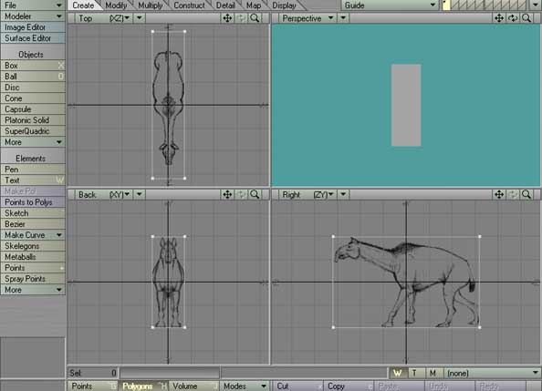
Fig 1. A box is drawn to check
the scale of the reference images.
Step 2. Leaving
the box, as a guide, you should now press 'd' (Display Options) and
click on Background Tab and the Automatic Sizing button(fig 2.). The top
image will
stretch to fit the box. We can then save all the backgrounds in one hit
via the presets
requester, ready to load straight in next for a next time.
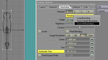
Fig 2. Auto Sizing is used to scale up top reference,
before saving the backgrounds as a preset.
Step
3. TRACING
THE TORSO
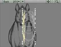
Right,
Now for the first bit of modeling! We are going to trace the side profile
of our
Dino, excluding the Head, Tail and Legs. Basically just the main Torso
for now. It is
preferable to deal with a complex model like this in sections, rather
than tackle it as
a whole. At a later stage we can digitally sew the various parts together.
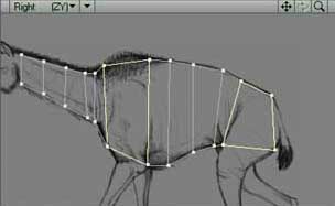
Fig 3. A cross section of
Macrachemia's
Torso.
With
the mouse and the Point tool (Press
+) trace the
outline of your creature, bearing
in mind that you will be turning this outline into quads (4
sided/ 4 pointed polygons),
and that you need to leave single quads for the back and front legs. Then
as Fig 3.
shows, you need to make adjacent quads running from the neck to the rear.
Step
4. EXTRUDING
Now
the Third D, we need to Extrude our profile (Press E) on the X axis, in
this case
to the outer edges of the stomach.
TIP:
Because we are working with quads (4 sided/ 4 pointed polygons) we can
easily flip between Nurb and
Poly mode. It is some times easier to make selections and navigate around
your model in poly mode, that's
the flat face, non curved version, and flip to Nurb (Press TAB), the curved
smooth version, occasionally to
monitor the progress of your model.
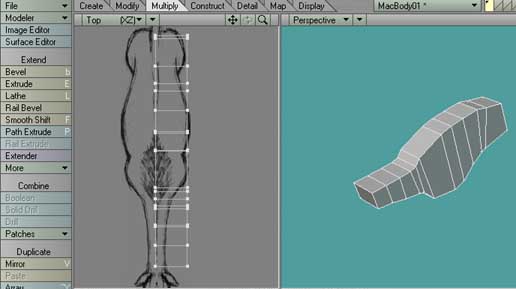
Fig
4. The Extruded Model
Step
5. Remove the
X facing polygons on X = 0, as shown here in Fig 5.
Fig
5. Polygons to be removed
Step
6. Now from
the top view we are ready to select and drag points in, to form the
shapes of the neck and stomach. The shape of the legs/thighs will be formed
in the
next few steps.
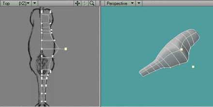
Fig
6. Points are dragged in to follow the shape of the top reference image.
NEXT
PAGE CLICK HERE . . . . TOP OF PAGE CLICK
HERE . . . .
|